From Drawing Set to Shared Building Language
Read plans, elevations, and sections together to understand a building’s design intent, resolve apparent conflicts, and ask more useful questions.
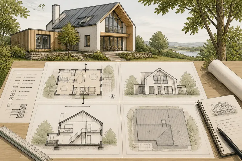
The most common mistake in reading building drawings is expecting one sheet to explain the whole building. A floor plan can make a room seem complete while leaving its height, exterior character, or connection to the roof unclear. The cost is not merely confusion: a reader may mistake a partial view for a contradiction, or carry an assumption into a conversation that the drawings could have clarified.
Plans, elevations, and sections are not competing pictures. Each cuts or looks at the building in a different way. Read together, they form a shared language for discussing what the design intends, even if you are not preparing to build or approve the work yourself.
Start by identifying what each view can show
A plan is a horizontal slice through a building, usually presented as if you were looking down after the portion above the cut had been removed. It is useful for understanding room arrangement, walls, openings, circulation, and the relationship between spaces. It does not, by itself, show the full height of a wall or the appearance of a façade.
An elevation is a straight-on view of one side of the building. It helps explain the exterior composition: windows and doors, roof outline, changes in cladding, and the relative heights of visible elements. An elevation generally does not show how rooms connect behind that façade.
A section is a vertical cut through the building. It reveals what a plan and elevation tend to leave unresolved: floor-to-ceiling relationships, roof shape, stair direction, and how spaces sit above, below, or beside one another. The section is especially useful where a building changes height or where an interior space opens through more than one level.
Before interpreting details, check the drawing title and view label. A sheet may contain several views, and an elevation may be named for the side of the building it depicts rather than the direction from which you happen to be looking.
When a room seems larger on the plan than it feels in the section
What usually causes it: A plan communicates width and length at one level, but it can conceal a low ceiling, a sloping roof, or a change in floor height. A large outline on paper can therefore describe a space that is broad but vertically constrained.
What to try, in order: Locate the room in the plan and note its label or identifying features. Then look for a section marker, often drawn as a line with arrows or a reference symbol, and find the matching section view. Compare the floor and ceiling lines there. If the section does not pass through the room, check for another section or a detail that cuts through the relevant area.
Do not assume that a blank patch in a section means the room is absent. The cut may simply pass elsewhere. A view only reveals what lies along its chosen line, with conventions for what appears beyond it.
When a window appears in one view but not another
What usually causes it: The views may show different sides or different levels of the building. A plan records an opening at the cut height, while an elevation shows a particular exterior face. A window high in a wall may not appear in a plan cut at ordinary door height, and a window on the opposite façade will not appear in the elevation you are studying.
What to try, in order: Check the elevation name and compare it with the plan’s orientation marker, if one is provided. Find the wall in question, then follow it to the exterior side shown in the relevant elevation. If the opening’s height or relation to the ceiling still seems unclear, look for a section through that wall or a window schedule identifying the opening.
Schedules and symbols add information, but they are not substitutes for matching the correct location and view. A repeated window symbol may refer to several openings whose positions differ.
When the roof looks inconsistent across sheets
What usually causes it: A roof is three-dimensional, but each drawing reduces it to a particular viewpoint. In plan, roof edges or overhangs may be shown above the rooms below. In elevation, the visible outline depends on which side is being viewed. In section, a cut can make a pitched or stepped roof profile easiest to understand.
What to try, in order: First distinguish a roof plan from a floor plan by reading the sheet title. Then compare the roof outline with the named elevations and any building sections. Look for repeated features, such as a ridge, valley, or change in roof height, rather than expecting every view to show the same silhouette. If a line’s meaning is unclear, inspect the legend or line conventions on the set.
Imagine you see a broad roof outline on a plan and a lower-looking roof edge in an elevation. If the section cuts through the roof’s slope, it may show that the apparent difference comes from the viewing angle rather than a design conflict. The useful result is a precise question—such as which roof plane the line represents—instead of a general claim that the sheets disagree.
When two sheets seem to contradict each other
What usually causes it: The drawings may be at different scales, cover different design stages, or show different kinds of information. A general arrangement plan may clarify spatial relationships, while a larger-scale detail explains a specific junction. A revision cloud or sheet date may also indicate that one view has been updated while another has not yet been coordinated.
What to try, in order: Check each sheet’s title, revision information, scale, and any notes about its purpose. Match the building location before comparing the lines. Then identify whether the apparent disagreement concerns position, height, material, or construction at a junction. Ask which drawing governs that particular question rather than assuming that the most visually detailed sheet governs everything.
For decisions that depend on a product label, manufacturer instructions, or local rules, consult those requirements and the responsible design professional. A general reader can identify the question, but should not treat a drawing interpretation as approval to alter safety-critical work.
When symbols and lines feel like a private code
What usually causes it: Drawings rely on conventions to compress information. A heavy line may indicate a cut wall, a lighter line may show something beyond the cut, and a dashed line may represent an overhead feature or hidden element. Symbols can point to another sheet, a detail, or a material note.
What to try, in order: Find the legend and general notes before guessing. Read the nearby callout, including its sheet reference, and follow it to the named detail if one is included. If the symbol is not explained, record its location and ask the project’s architect, designer, or builder what it denotes. Avoid assigning a meaning solely because the mark resembles a familiar symbol from another set.
A useful question names both the mark and its location: “What does this dashed line above the kitchen indicate?” That gives the person answering a place to start and makes it easier to point to the relevant view.
How do plans, elevations, and sections work together?
Which drawing should I read first?
Begin with the sheet index and the overall floor plan, which establish where the rooms and major elements sit. Then use elevations for exterior appearance and sections for height and vertical connections.
Can a floor plan show ceiling height?
Usually not clearly on its own, because the plan is a horizontal cut rather than a vertical view. Look for ceiling notes, a reflected ceiling plan, or a section through the room.
Why are some walls drawn with heavier lines?
Line weight often distinguishes elements cut by the plan from features farther away, but conventions vary by drawing set. Check the legend and notes before using line weight to infer a wall’s role.
What should I ask when a drawing still feels ambiguous?
Point to a specific location and describe what you can see in each relevant view. Ask which sheet or detail clarifies the feature, and whether the information represents the current design revision.
Use the three views to make a clearer question
A practical reading habit is to move between views by location rather than by sheet order. Choose one feature—a stair, a window, a tall room, or a roof edge—and find it in the plan. Check its exterior face in the matching elevation, then look for a section that passes through or near it. Each view should answer a different part of the question.
For a general reader, the aim is not to reconstruct every hidden component. It is to separate what the drawing directly shows from what remains uncertain, then ask about the uncertainty in terms the project team can answer. Reading plans, elevations, and sections together makes design intent easier to discuss because it replaces a single impression with three specific views. Keep the sheet reference and location beside your question; that small habit makes the shared building language useful beyond the page.